Change Language :
Plain bearings - Installation and tolerances

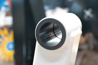
What is the tolerance for the housing bore?
iglidur plain bearings are press-fit bearings that are pressed into an H7-toleranced housing bore with oversize. A tolerance of at least h9 is recommended for the shafts. Their inner diameter is only set after the press-fit into the H7 housing bore. The press-fit excess dimension can be up to 2% of the inner diameter. This ensures a secure press-fit of the bushings and avoids axial and radial displacements in the housing.
The hole in the housing should be manufactured to tolerance H7 for all bearings and be as smooth, even and chamfered as possible. Assembly is carried out with a flat press as the use of centring or calibrating pins can damage the bearing and lead to greater clearance.
ISO tolerances for iglidur plain bearings [mm]
| Diameter d1 | Housing H7 | Shaft h9 | E10 (tolerances according to ISO 3547-1) | E11 (tolerances according to ISO 3547-1) | F10 (tolerances according to ISO 3547-1) | D11 (tolerances according to ISO 3547-1) |
|---|---|---|---|---|---|---|
| up to 3 | +0.000 +0.010 | -0.025 +0.000 | +0.014 +0.054 | +0.014 +0.074 | +0.006 +0.046 | +0.020 +0.080 |
| > 3 up to 6 | +0.000 +0.012 | -0.030 +0.000 | +0.020 +0.068 | +0.020 +0.095 | +0.010 +0.058 | +0.030 +0.105 |
| > 6 up to 10 | +0.000 +0.015 | -0.036 +0.000 | +0.025 +0.083 | +0.025 +0.115 | +0.013 +0.071 | +0.040 +0.130 |
| > 10 up to 18 | +0.000 +0.018 | -0.043 +0.000 | +0.032 +0.102 | +0.032 +0.142 | +0.016 +0.086 | +0.050 +0.160 |
| > 18 up to 30 | +0.000 +0.021 | -0.052 +0.000 | +0.040 +0.124 | +0.040 +0.170 | +0.020 +0.104 | +0.065 +0.195 |
| > 30 up to 50 | +0.000 +0.025 | -0.062 +0.000 | +0.050 +0.150 | +0.050 +0.210 | +0.025 +0.125 | +0.080 +0.240 |
| >50 to 80 | +0.000 +0.030 | -0.074 +0.000 | +0.060 +0.180 | +0.060 +0.250 | +0.030 +0.150 | +0.100 +0.290 |
| >80 to 120 | +0.000 +0.035 | -0.087 +0.000 | +0.072 +0.212 | +0.072 +0.292 | +0.036 +0.176 | +0.120 +0.340 |
| > 120 up to 180 | +0.000 +0.040 | -0.100 +0.000 | +0.085 +0.245 | +0.085 +0.335 | +0.043 +0.203 | +0.145 +0.395 |

Our most widely read white paper
Tolerances, installation, measurement
Why is our white paper Plastic bearings: tolerances, installation, measurement so popular? Because it puts an end to the most common sources of error in day-to-day work with plastic bearings:
❌ Incorrect tolerance design
❌ Incorrect measurement of plain bearings
❌ Damage to the bearings due to incorrect installation
The white paper covers the following topics, among others:
Tolerance design for correct bearing clearance
✅ Press-fit and bearing clearance
✅ Moisture absorption
✅ Thermal expansion of plastic
✅ Recommended tolerances
How to measure plastic plain bearings correctly
✅ Measuring plain bearings correctly
✅ Checking the inner diameter
Installing plastic bearings correctly
✅ Importance of installation tolerances
✅ Preparation of the housing bore
Recommended tolerances
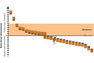
The installation height and tolerances of the iglidur plain bearing depend on the material and the wall thickness. Moisture absorption and thermal expansion are decisive for the material. Plain bearings with low moisture absorption can be installed with a small bearing clearance. The following applies to the wall thickness: the thicker the bearing, the greater the bearing clearance must be.
This results in different tolerance classes for iglidur plain bearings. With these tolerances, iglidur plain bearings can be operated in accordance with the installation recommendations in the respective permissible temperature range and at humidity levels of up to 70%. At higher humidity or if the bearings are operated under water, materials with low moisture absorption are preferable.
Various press-fit methods
Hydraulic or mechanical
The most common method is the mechanical press-fit of the plain bearing using a hand press. A flat press-fit punch is used to press the plain bearing into the housing bore. A centring or calibrating pin should not be used, as this may lead to cracks along the weld line and a larger bearing clearance.
Without a press
If no press is available or circumstances do not allow the use of a press, the plain bearing can be carefully assembled with a rubber mallet. A piece of wood between the plain bearing and the wood can help to protect the bearing from damage.
Automated assembly
When implementing (partially) automated assembly, the correct feeding and positioning of the components is particularly important. It can make sense to optimise the component geometry for the process. With plastic plain bearings, there are virtually no limits to the design. Geometries with conical diameters, grooves or anti-rotation devices can be realised cost-effectively.
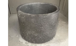
igutex plain bearing after shrinking
Shrinking
Cooling the plain bearings can help to make plain bearings easier to press-fit. The bushings are cooled using liquid nitrogen, shrink together and are therefore easier to fit. Before shrinking, the bearings must be thoroughly cleaned and checked for damage. Once they have been reheated, the material expands again and the bearing sits firmly in the housing bore.
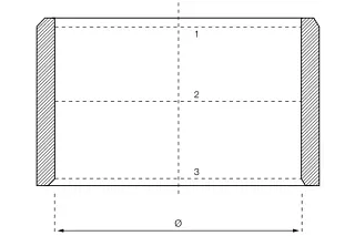
The position of the measuring levels (1, 2, 3 = measuring lines)
Checking the bearing seat
iglidur plain bearings are press-fit bearings for housings with an H7 unit bore. This press-fit of the bearing secures the bearing in the housing on the one hand, and on the other hand the inner diameter of the plain bearing is formed as a result. The bearing is tested, installed in the hole with the smallest dimension, both with a dial gauge and with a plug gauge.
- Pressed into the hole, the good side of the plug gauge must pass the bearing smoothly
- With a slide tester, it should be ensured that the inner diameter of the bearing must be within the specified tolerance on average at the measuring planes (see diagram opposite)
Locating spigot
Plain bearings actually "migrate" out of the housing bore if the press-fit is lost. Plain bearings are often fastened by press-fit in a slightly narrower tolerance housing. Under mechanical tension, the bearing sits firmly in the hole. If this mechanical tension is reduced due to high temperatures or permanent exceeding of the permissible load, the press-fit is also reduced.
Of course, it can also happen that the manufacturing tolerances of the housing bore are so inaccurate that the hole is not sufficiently undersized. In this case too, the bearing cannot build up sufficient tension to create an press-fit. The result is extreme wear of the plain bearing. The solution to the problem is a locating spigot of the plain bearing. You can find out what options are available for axially securing the plain bearings in our factsheet under the topic "locating spigot".
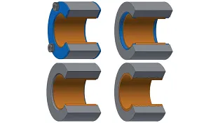
Installation of igutex fibre composite bearings
igutex plain bearings can be installed using a flat press, flat plate or press-fit pin. The press-fit pin must not have sharp edges. An undercut at the flange transition helps prevent damage. Installation by hammering, e.g. with a hammer, is not recommended as this can damage the fibre composite plain bearing.

Gluing in plain bearings
Plain bearings are usually pressed or clamped into the housing bore. This ensures that they sit firmly in the hole and do not rotate unintentionally. But what if this is not possible due to manufacturing tolerances? Or if the plain bearing is even supposed to rotate?
Even if it is not part of the standard repertoire of many plain bearings, plastic bearings can also slide on the outer diameter. This is why plastic bearings are used. The bearing is placed on a bolt and should then - together with the bolt - rotate in something or roll on something. Gluing seems to be a good solution. But there are probably as many adhesives as there are bearing materials. Which is the right one?
Guidelines for machining
iglidur plain bearings are supplied ready for installation. The comprehensive product range allows the use of standard dimensions in most cases. If subsequent machining of the plain bearing is nevertheless necessary, the adjacent table shows the machining guidelines. If possible, however, subsequent machining of the sliding surfaces should be avoided. Higher abrasion is usually the result. One exception is e.g. iglidur M250, which is very suitable for subsequent machining. With the other iglidur plain bearings, the disadvantages of machining the sliding surfaces can be counteracted by using assembly lubrication.
| Process | Turning | Drilling | Milling |
|---|---|---|---|
| Tool material | Stainless steel | Stainless steel | Stainless steel |
| Feed rate [mm] | 0.1 ... 0.5 | 0.1 ... 0.5 | to 0.5 |
| Clearance angle | 5 ... 15 | 10 ... 12 | |
| Clamping angle | 0 ... 10 | 3 ... 5 | |
| Cutting speed [m/min] | 200 ... 500 | 50 ... 100 | up to 1000 |
Consulting
I look forward to answering your questions
Conlog LTD (Stocking Distributor)+972 3 9269595Write e-mail
Shipping and consultation
In person:
Monday to Friday from 7 am - 8 pm.
Saturdays from 8 am- 12 pm.
Online:
24h
WhatsApp-Service:
Montag – Freitag: 8 – 16 Uhr